Included With Your Scanner
|
Scanner |
AC Adapter |
Vehicle Accessory Power Cord |
|
Three-Wire Harness |
Mounting Bracket and Hardware |
Antenna |
|
Serial Programming Cable |
O/M on CD ROM |
Other Printed Materials |
|
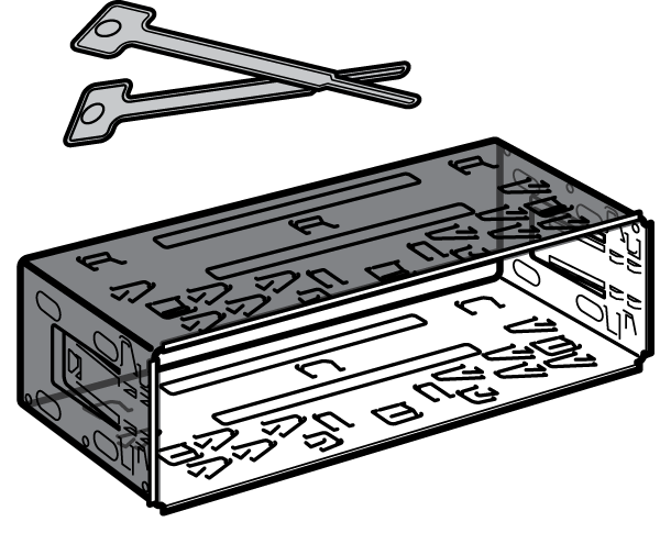
Mounting Sleeve and keys (Optional for BCT15X; Included with BCD996XT) |
||


Setting Up Your Scanner
These guidelines will help you install and set up your new scanner: The scanner can be placed on a convenient surface in your home as a base station, and connected to a standard outlet that supplies 120VAC, 60Hz. You must use either the supplied antenna or an electrically correct outdoor antenna, properly and safely mounted at your chosen site. The scanner is also designed to accommodate either DIN-E and ISO-DIN automotive mounting configurations using a DIN-E sleeve and keys, (Part Number DIN-0001, BCD996XT: Included; BCT15X: Optional). The unit can also be placed above, beneath, or in the dash of your vehicle using the supplied bracket and mounting hardware.- If your scanner receives interference or electrical noise, move the scanner or its antenna away from the source.
- To improve the scanner’s reception, use an optional external antenna designed for multi-band coverage. (You can purchase this type of antenna at a local electronics store). If the optional antenna has no cable, use 50Ω coaxial cable for lead-in. A mating plug might be necessary for the optional antennas.
- Use an optional stereo earphone or sterreo headset with proper impedance (32 Ω) for private listening. Read the precautions at General Precautions.
- Do not use the scanner in high-moisture environments such as the kitchen or bathroom.
- Avoid placing the scanner in direct sunlight or near heating elements or vents.
Power Related Issues
Important: To prevent memory from being corrupted, do not unplug the AC adapter during the time the memory is accessed for programming or auto store. Notes:- If when you connect the AC adapter the [VOL] /Power Switch is ON, the scanner may not power on. Should this occur, simply turn the control OFF, then ON again.
- If the scanner loses power (as when you turn off your car’s ignition with the scanner’s power switch on), it can lose some system settings such as display color and backlight. To ensure that such settings persist, either change the setting using the scanner’s menu or power the scanner off then back on using the power switch after making such setting changes.
Base Station
This is the simplest approach to let you get started quickly. Decide on a location that is convenient to a nearby wall outlet, has desk space to let you complete your programming worksheets, will safely allow the indoor antenna to be extended, or near a window to use an outdoor antenna. To secure the radio to a surface, by means of the mounting bracket, follow the steps below:
 - Attach the four protective mounting feet to the mounting bracket when you casually use the scanner on a flat surface. Should you desire to permanently mount the scanner, remove the feet and use wood screws through the bracket as described in Steps 2 and 3.
- Use the bracket as a template to mark positions for the two mounting screws.
- At the marked positions, drill holes slightly smaller than the screws.
- Align the bracket with the threaded holes on the sides of the radio case so the bracket is beneath the radio. Secure the bracket using the two threaded knobs. Never overtighten the knobs.
Setting Up an Audio Recording Device or Computer Recording
It is best if you plan ahead when you initiate the basic setup of the scanner if you include the components to record incoming reception. You need an audio recording device which can be controlled by a Voice Operated module (VOX) either externally or from within the unit and the correct connecting cable. The REC (record) jack on the rear apron provides a constant-level audio output which is not affected by the setting of the volume control. Use a mono or stereo cable that ends in a 3.5mm plug for the scanner. The recorder might have its own requirements as to the proper plug. Check the recorder’s instructions to be sure. Connect the cable to an external or internal VOX control so that the recorder operates when audio is present. You can also connect the cable to the appropriate input jack on your PC so that with controlling software, you can record to your hard disk. In order for the function to operate, you must set the channel to record. You must also set the system’s record option to either All Channel, which will record all channels regardless of any channel’s setting, or Marked Channel which only lets recording occur if you have selected record for that channel. Which you choose will depend on various factors.Vehicle Installation
You can mount your scanner in your vehicle, using either the supplied bracket or the optional DIN-E sleeve.Mounting Using the Bracket
With the bracket removed from the radio, use the holes in the bracket as a template to initially mark the location you plan to use in your vehicle. Be absolutely certain of what might be behind the mounting surface before making any holes, be it above, or below, or in front of your dash, armrest console, or other location. If you drill carelessly, expensive damage can result. If in doubt, consult your vehicle dealer’s service department or a qualified professional installer. Important: AVOID AIRBAG DEPLOYMENT ZONES. Ignoring this installation concern may result in bodily harm and the inability of the airbag to perform properly.
- Using appropriate screws or other hardware, secure the bracket.
- Insert the scanner and insert the bracket knobs to lock the scanner in position.
- Attach the Cigarette Lighter Power Cord to the rear of the scanner and plug the adapter end into a dash mounted 12V DC socket.
- Attach a suitable mounted mobile antenna to the antenna jack on the back of the scanner.
Mounting Using the DIN-E Sleeve (Option for BCT15X)
If you are unsure about how to install your scanner in your vehicle using the optional DIN-E sleeve, consult your automobile manufacturer, dealer, or a qualified installer. Before installing, confirm that your scanner fits in the desired mounting area and you have all the necessary materials to complete the task. Your scanner requires a 2 x 7-1/8 x 5-5/16 inch (50 x 180 x 135 mm) mounting area. Allow an additional 2-3/8 inch (60mm) space behind the unit for connectors and wires.
- Remove the bracket if it is attached.
- Remove the four Philips screws from four small tabs on the rear of the case that secure the outer metal case and pull off the case (toward the rear) with care.
- Install the DIN sleeve into the opening in your dashboard, lip facing out.
- Push out the top and bottom tabs to hold the sleeve firmly in place.
- Before inserting the scanner in the sleeve, attach the cable from the previously mounted antenna. Attach the DC Power leads. RED goes to a positive (+)connection on your fuse block while BLACK connects to the vehicle’s chassis ground (-).
- Connect the ORANGE lead to one side of the headlamp switch so that when you activate the headlights, the scanner’s LCD display changes intensity. Be sure all the connections are routed away from any potentially pinching or slicing sheet metal.
- Slowly slide the scanner into the sleeve until it locks in place.
- To remove the unit, fully insert the removal keys into each slot on the left and right edges of the front panel. Carefully slide the radio from the sleeve.
Removing the Scanner from the DIN-E Sleeve
If you plan to connect other devices or wires to the radio, such as a GPS unit, at a later time, you should plan to remove the scanner from the DIN-E sleeve. This is easily done using the provided Removal Keys that come with the optional DIN-E sleeve. Refer to the illustration that follows, showing the Removal Keys. Fully insert both Removal Keys into the slots on the left and the right edges of the radio’s dress panel. You cannot remove the radio with only one key. Press in fully,and do not twist the keys. The radio will unlock from the sleeve making withdrawal from the sleeve possible. Store the keys in a safe place for future use.  |
 |
Mounting Using ISO Technique
Some vehicles can take advantage of another approach to mounting a radio in a vehicle, called the ISO technique. However, this technique requires a very detailed and thorough knowledge of the technique. Therefore, we strongly suggest that if you have any doubt about your experience and abilities, please consult with a professional installer who is familiar with the ISO approach to radio installation. To begin the process, it is first necessary to remove the scanner’s outer metal sleeve from the inner chassis. Unthread the four screws in the rear of the unit. Slide the cover toward the rear and off. Once the sleeve is removed, you will see threaded, metric machine screw holes on either side of the chassis cabinet. Uniden does not supply these screws. Their diameter, length, and screw type should be chosen by a qualified installer based on the internal vehicle bracket which will be used in securing the scanner chassis. Once the original radio is removed from the vehicle dash and the fit of the scanner is correct, be sure to connect all the power, audio, antenna, and any other cables or wires, to the scanner before the scanner is secured. The following illustration is a typical example of the ISO technique and the general side mounting screw holes often encountered. It does not actually represent the Uniden scanner nor your vehicle’s mounting bracket. Only a professional installer will be able to determine the best and correct approach.  |
 |
Removing the Display Sticker
Before you use the scanner for the first time, remove the protective plastic film over the display.Connecting an Optional Antenna
The scanner’s BNC connector makes it easy to connect a variety of optional antennas, including an external mobile antenna or outdoor base station antenna. Note: Always use 50-ohm, RG-58, or RG-8, BNC terminated coaxial cable to connect an outdoor antenna. If the antenna is over 50 feet from the scanner, use RG-8 low-loss dielectric coaxial cable. Cable loss increases with higher frequency.Connecting an Earphone/Headphone
For private listening, you can plug a 1/8-inch (3.5 mm) mini-plug earphone or headphones (not supplied) into the headphone jack on the front of your scanner. This automatically disconnects the internal speaker. See the Earphone Warning for important information about using an earphone/headphone.WARNING! Never connect anything other than the recommended amplified extension speaker to the scanner’s headphone jack. Damage to the scanner might occur.
Connecting an Extension Speaker
In a noisy area, an optional amplified extension speaker, positioned in the right place, might provide more comfortable listening. Plug the speaker cable’s 1/8-inch (3.5-mm) mini-plug into your scanner’s back-panel Ext. Sp. Jack.WARNING! Never connect any part of the headphone jack to the antenna jack or connect the radio to an installation where the antenna and audio connection are grounded. This might also damage the scanner.
| This page applies to the following scanner(s): BCD996XT BCT15X Users Guide |